Main Cylinders
For most of the photos on this page, you can click the image for a larger picture.
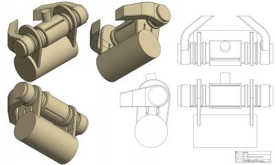 |
Keith, our CAD Modeller, has been working on the cores for the pattern. The cores will make the steam spaces within the cylinders, e.g. the motion cylinder space, the valve cylinder space and the transfer ports. Here you can see the CAD model of the cores.
Tony says " what we are seeing in Keith's CAD model is the beginning of a process showing what amounts to developing the 'space' within the finished casting and from this CAD model and the 2D drawings Keith will produce, I will make ' core boxes' which are the negative of what we are seeing on the screen at present and will be used to make the sand cores of the type we saw at the foundry. In effect then, Keith is modelling me a 'solid' so I can produce a 'negative' to produce a 'solid' to make a 'hole' in the sand mould." The model will need to be split into 4 sections which match the 4 layers of the main pattern. |
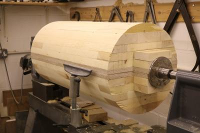 |
Over the winter, Tony has been working on the smaller, valve cylinder. This cylinder sits above the motion cylinder and controls the admission into and exhaust out of the motion cylinder |
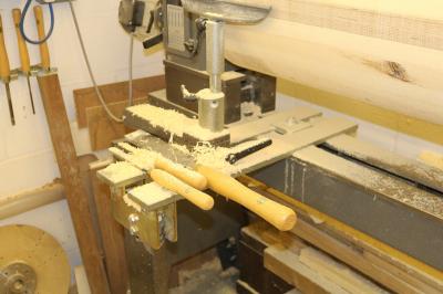 |
The wood turners tools! |
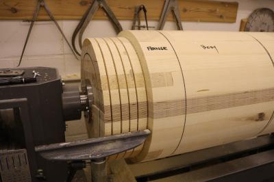 |
Tony turns the rough blank to parallel. This is accomplished with a small spirit level (usually seen on the bed of the tailstock) and a long steel rule. The blank is sized using a pair of very old calipers and measurements straight off the drawing. Tony then marks the main sections of the valve cylinder and turning to final size can start. The "slots" cut in the end are depth telltales put in with a parting tool and which is marked with sticky tape. Tony can quite merrily cut down to the depths without having to constantly check with calipers. |
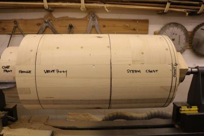 |
Tony has now got the end of the pattern down to a quarter of an inch of the final outside diameter dimension and has marked up the pattern. The core print will be to support the end of the core mould. Once Tony has finished roughing down the other areas he will set a datum line from which the finished measurements will be referenced. |
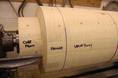 |
A view of the print end |
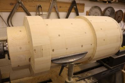 |
The valve cylinder pattern continues to take shape |
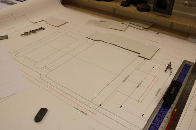 |
Tony has made up some templates to assist in getting the right final profile for the valve cylinder. He says "these two simple templates will give me reference on the finishing cuts. Tomorrow I'll start at the print end with a reference cut and all measurements will come from that. I'll take the print down to size plus an allowance for draw and sanding. On the lathe, sanding is quite easy so when it comes off the lathe the section is ready for the first coat of paint. In the case of the valve cylinder there are a number of additions so I'll not paint until all the bits are added. It's starting to progress now and shortly I'll be able to finish making the blank for the second half of the valve cylinder and get that on the lathe." |
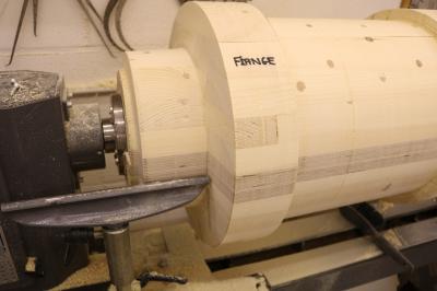 |
The print end is now down to sanding size. Tony says that he will get the flange down to sanding size tomorrow |
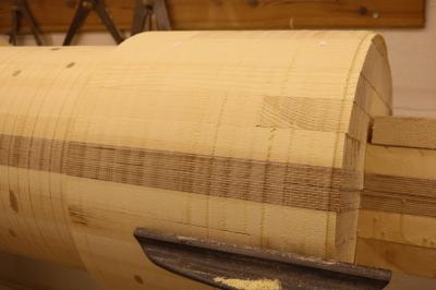 |
The steam chest end is almost down to size. |


